

The project page
The project page
Section titled “The project page”The project page is the workshop: the sheet and the parts on one side, the settings on the other, the part cards below. The bar above sums up the job — parts, dropped files, area, sheets estimated at this spacing, best possible density.
The sheets
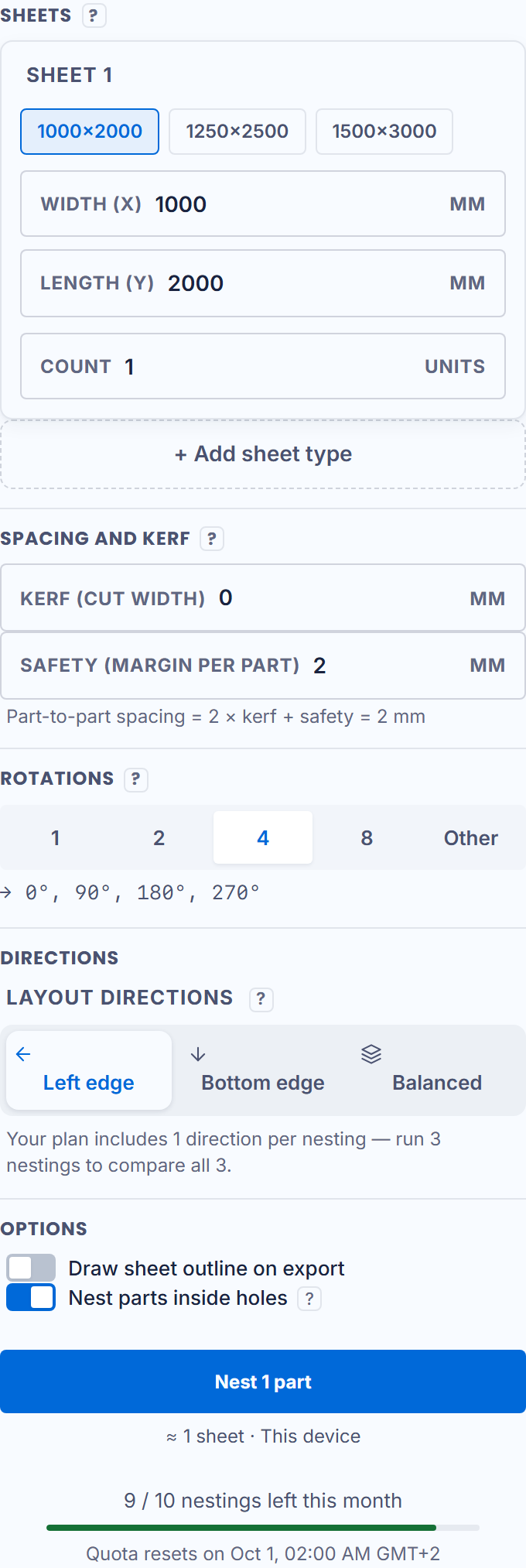
Section titled “The sheets”As many sheet types as your stock: width (X), length (Y) and quantity of each type, with standard industry sizes to save time. One format is enough? One line. Full sheets and offcuts? Two lines. On the free plan, each job stops at 2 sheets.
The spacing
Section titled “The spacing”This is THE setting that protects your parts: the rule is written under the field — spacing = 2 × kerf + safety. The kerf (cut width) is what your torch eats; the safety is your margin per part. Spacing finer than 0.05 mm triggers a warning: finer than a laser kerf, parts may touch at cutting.
The rotations
Section titled “The rotations”The allowed angle step: 90° for rectangles, 180° when upside down does not matter, a finer step to save more material. “No rotation” keeps every part at 0° — the choice for oriented engraving.
The layout direction
Section titled “The layout direction”Which edge the parts pack against: left edge, bottom edge, or a balance of both — in the drawing’s coordinate system, the on-screen arrow shows the way. Fewer directions checked, faster result. On the free plan, one direction.
The options
Section titled “The options”- Nest parts inside holes: small parts can settle in the cutouts of large ones. Beyond 2.4 mm of spacing the option disables itself — an engine limit, said on screen;
- Draw sheet outline on export: adds the sheet rectangle to the DXF so the machine sees the stock boundary.
The Nest button starts the computing; a Cancel button appears while the engine runs.